Showing posts with label led. Show all posts

Tuesday, February 4, 2014

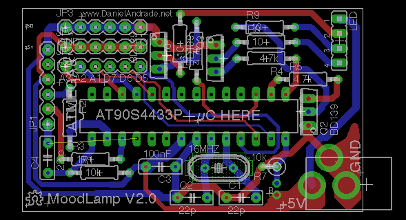
Hardware MoodLamp Based on LED

Long time ago I came across this page http://tobe.nimio.info/project/moodlamp, where Toon Beerten created a Moodlamp using a PIC16F628 µC. I remember that back then I didn’t have much knowledge on µC’s programming, so the first thing I did was to buy a Arduino board, and since that time I have been learning a lot and making many different projects with it…


 Open Hardware MoodLamp Based on LED 
 
Time has passed, I’ve built the breadboard prototype, then the first version, using only one layer (which is a good version if you want to etch your own PCB). Always wanted to make the project public as an Open Hardware, but due my lack of time, I never did, until I arrive in Genova. I then decided to make a second version of the board, two layers, the ability to program the µC without removing it from the socket (for programing you will need an Arduino, FTDI or USB-to-serial cable) and some available pins for those who want’s to add more features to the board, like a temperature sensor or another kind of sensor.

Here you will find the information on how to build your own MoodLamp with simple electronic components. I am also planing on selling the MoodLamp kits, if you are interested, please leave a comment below (you can always make a Paypal donation so I can buy some beers!)


Continue Reading..

Thursday, October 3, 2013

Mains Powered White LED Lamp

Did it ever occur to you that an array of white LEDs can be used as a small lamp for the living room? If not, read on. LED lamps are available ready-made, look exactly the same as standard halogen lamps and can be fitted in a standard 230-V light fitting. We opened one, and as expected, a capacitor has been used to drop the voltage from 230 V to the voltage suitable for the LEDs. This method is cheaper and smaller compared to using a transformer. The lamp uses only 1 watt and therefore also gives off less light than, say, a 20 W halogen lamp. The light is also somewhat bluer. The circuit operates in the following manner: C1 behaves as a voltage dropping ‘resistor’ and ensures that the current is not too high (about 12 mA).

Mains Operated White LED Lamp Circuit
The bridge rectifier turns the AC voltage into a DC voltage. LEDs can only operate from a DC voltage. They will even fail when the negative voltage is greater then 5 V. The electrolytic capacitor has a double function: it ensures that there is sufficient voltage to light the LEDs when the mains voltage is less than the forward voltage of the LEDs and it takes care of the inrush current peak that occurs when the mains is switched on. This current pulse could otherwise damage the LEDs. Then there is the 560-ohm resistor, it ensures that the current through the LED is more constant and therefore the light output is more uniform.

White LED Lamp Circuit Diagram
There is a voltage drop of 6.7 V across the 560-Ω resistor, that is, 12 mA flows through the LEDs. This is a safe value. The total voltage drop across the LEDs is therefore 15 LEDs times 3 V or about 45 V. The voltage across the electrolytic capacitor is a little more than 52V. To understand how C1 functions, we can calculate the impedance (that is, resistance to AC voltage) as follows: 1/(2π·f·C), or: 1/ (2·3.14·50·220·10-9)= 14k4. When we multiply this with 12 mA, we get a voltage drop across the capacitor of 173 V. This works quite well, since the 173-V capacitor voltage plus the 52-V LED voltage equals 225 V. Close enough to the mains voltage, which is officially 230 V.

Mains Powered White LED Lamp Circuit DiagramMoreover, the latter calculation is not very accurate because the mains voltage is in practice not quite sinusoidal. Furthermore, the mains voltage from which 50-V DC has been removed is far from sinusoidal. Finally, if you need lots of white LEDs then it is worth considering buying one of these lamps and smashing the bulb with a hammer (with a cloth or bag around the bulb to prevent flying glass!) and salvaging the LEDs from it. This can be much cheaper than buying individual LEDs…
Continue Reading..

Tuesday, September 10, 2013

Current Controlled Boost LED Driver and Black Soldermasks

The MAX16834 is a neat little chip (its not the only one, there are plenty of others out there) that allows high efficiency designs for LED string driving. It provides a platform for a Buck or Boost converter design, as well as brightness adjustment via analog/PWM input pins, as well as a fault output (in case of open/short circuits for example) and also diverse other functionalities that can be quite useful.


Continue Reading..

Friday, April 12, 2013

Flip Flop Led Circuit

Flip Flop LED
Flip flop circuit is a series of free runing multivibrator given the burden of LEDs on each side of the transition changes its output signal. Flip flop circuit with LEDs is quite simple, that is prepared with 2 units and 2 units of 2N3904 transistor circuit tank circuit composed by the RC circuit. 
LED indicators signal a change that is placed on each side of the flip flop will be lit in turn by the fire and extinguished the same as the charge and discharge capacitor. Flip flop circuit is quite simple as shown in the picture below.

Flip Flop LED series

The working principle is the flip flop over when the series voltage source is given then the 10uF capacitor will be charged through R 470 and the LED will then be forwarded to triger the transistor base so that the transistor will turn ON and LEDs. this occurs alternately on each side, so that the LED light will illuminate in turn as well.
Continue Reading..

Tuesday, April 9, 2013

Regulated 24 Watt Broad Spectrum LED


This project involves constructing an energy efficient broad spectrum LED lamp system. The lamp is useful for indoor reflective room lighting. It has a broad color spectrum that more closely approximates the light of the sun when compared to fluorescent bulbs and white-only LEDs. The light level is regulated and the light that is produced does not flicker. The six differently colored LED stars, made by LedEngin, Inc., are rated at 5 watts (nominal). The LED array and associated current regulator consume 1 amp at 24VDC (24 Watts). NEVER stare directly at this lamp when it is running at full operating power, it is DANGEROUSLY BRIGHT.

Regulated 24 Watt Broad Spectrum LED Circuit diagram : 


With the LEDs shown, the combined color of the lamp has a pinkish white hue. The 5 Watt ratings of the LEDs are not precise, the white, blue and green LEDs consume about 4W and the lower voltage red, orange and deep red LEDs consume about 3W. The current regulator keeps the LED brightness constant and insures that the LED series string never draws more than 1 amp of current.

The project has also been coined "Bold as LED" in reference to the Jimi Hendrix song "Bold as Love" which has the lyric: "My yellow in this case is not so mellow"

Specifications:


  • Nominal operating power: 24 Watts (24V DC at 1 Amp)
  • LED power consumption above regulation point: 18.6 Watts
  • Maximum operating voltage: 28V DC
  • Minimum voltage for regulated light: 23V DC
  • Leds produce light down to 11V
  • Deep Red LED voltage: 2.55V
  • Red LED voltage: 2.37V
  • Amber LED voltage: 2.60V
  • Green LED voltage: 3.92V
  • Blue LED voltage: 3.56V
  • White LED voltage: 3.7V
  • Voltage across regulator when current becomes regulated: 4.2V

Theory:

The lamp is wired as a current loop which includes the power supply, the LED series string and the 1 amp current regulator circuit. The LM317K and 1.2 ohm 5 Watt resistor act as a current regulator that limits the loop current to 1 Amp. During regulation, there will always be 1.2V across the 1.2 ohm resistor. The current regulator insures that the LEDs always run at their maximum brightness, but not so bright that they burn out. A 100uF electrolytic capacitor bypasses the DC power input to the device and a 100nF monoblock capacitor bypasses the LM317K input.

Construction:

The LEDs and current regulator circuit were mounted on a 3" x 8" chunk of 1/8" aluminum stock. The LM317K regulator and LED heat sinks were bolted to the chassis directly, heat sink grease was used on the regulator, the heat sinks and the six LEDs. Connecting the LM317K directly to the aluminum plate makes the plate electrically hot at 1.2V, the plate should not be allowed to come into contact with any live conductors. By using a few more parts, the LM317 can be mounted with an insulator and plastic shoulder washers for electrical isolation from the mounting plate.

The LEDs come mounted on their own small star-shaped aluminum substrates, these were attached to the aluminum plate using two 7/16" 4-40 screws and nuts per LED. A drop of silicone heat sink grease should be applied to the center of each LED star when it is mounted to the plate for heat conduction. It is important to use insulating plastic washers on the top side of the LED stars to prevent electrical contact with head of the screw. The LED stars were soldered together using short pieces of #20 tinned wire after being mounted on the plate. It is necessary to use a fair amount of heat to solder the contacts, a 200/240W soldering gun did the job. Be very careful not to melt the lenses on the LEDs, the LEDs cost around $10 each. The positive and negative leads of the LED series string were connected back to the current reglator circuitry using #20 wire covered with teflon insulation.

The initial mechanical arrangement did not pass the "rule of thumb" test, which says that if a semiconductor is too hot to hold your thumb on, it will not live a long life. Two large aluminum heat sinks were bolted to the back of the aluminum plate and seem to be sufficient to keep the lamp operating at a reasonable temperature. The LED array produces more heat than the LM317K.

Use:

Connect this circuit to a 24VDC power supply or other power source such as a solar-charged lead acid battery. Be sure to observe the correct polarity. Look away from the LEDs and apply power. Again, do not stare directly at the LEDs, they are bright enough to harm your vision. A switch-mode power supply rated at 24VDC and 1 Amp or more is probably the most energy-efficient way to power this device from line power.

Parts:


  • 1x LM317K T03 case 1.5A adjustable voltage regulator
  • 1x 1.2 ohm 5W resistor (or 2x 2.4 ohm 2W resistors in parallel)
  • 1x 100uF 35V or higher electrolytic capacitor
  • 1x 100nF 35V or higher monolythic capacitor
  • 1x LedEngin LZ1-10R205 deep red 5W LED
  • 1x LedEngin LZ1-10R105 red 5W LED
  • 1x LedEngin LZ1-10A105 amber 5W LED
  • 1x LedEngin LZ1-10G105 green 5W LED
  • 1x LedEngin LZ1-10B105 blue 5W LED
  • 1x LedEngin LZ1-10CW05 cool white 5W LED
  • Miscellaneous wire, solder lugs, termination strips and hardware,
  • Large aluminum mounting plate, heat sinks if necessary.

Continue Reading..

Monday, April 8, 2013

VU LED Indicator Schematic

VU LED indicator is simpler and smaller than their analog, and very common in audio equipment. This version is based on National Semiconductor IC, and using the logarithmic version. Each LED operates with a 3dB difference from before, and the jumper is provided to allow dot or bar mode.


The circuit is completely conventional, and is based on application notes from National Semiconductor. The circuit is shown in the picture below and you can view it with a single IC and some discrete components. DC to the LED is almost filtered - C1 are included to ensure that the IC does not oscillate, and is not a filter cap.


This allows a higher LED current with lower dissipation than is the case if the DC is fully refined, and full smoothing would also require much larger capacitors. This will increase the size and cost of the project - especially important if you want to use in larger quantities that may occur with a mixer or analyzer.It could not be simpler. At the maximum level that you want to operate the equipment (as shown on the audio millivoltmeter or an oscilloscope with a signal applied), adjust VR1 so that the signal light to all the green LED (L1 is the most sensitive, and L10 showed the maximum level, so L1 to L8 should be lit ). If the input directly from the speaker output, an additional series resistor should be used in terminal "Aud" input to reduce the level. This can be determined by calculation (I leave it to you) or by experiment. As a guide, for 50W amplifier, an external resistance should be about 47k ohms.If you calibrate the meter for the power amplifier, set the output to a level below clipping. Adjust the level control until the LED turns on. In this way, if (L10) LED bulbs last when youre listening to music, youll know that you are very close to clipping, and volume should be reduced.
Continue Reading..

Saturday, March 23, 2013

Simple Current Controlled LED Tube Light Circuit Diagram

Note: This circuit is developed by Mr.Seetharaman for readers of CircuitsToday. This particular circuit has been kept so simple for people who has limited access to components or in other words this is an emergency light that you can build with minimum components. In addition to circuit diagram, He has shared photographs of the prototype he made in National emergency light and a PCB design.
 

Simple Current Controlled LED Tube Light Circuit Diagram
Continue Reading..

How to Make a LED Bulb Circuit

LEDs are being Incorporated in vast magnitudes today for everything that may involve lights and illuminations. White LEDs have especially become very popular due to their mini size, dramatic illuminating capabilities and high efficiency with power consumptions.


In one of my earlier post I discussed how to make a super simple LED tube light circuit, here the concept is quite similar but the product is a bit different with its specs.

Here we are discussing the making of a simple LED bulb CIRCUIT DIAGRAM

By the word "bulb" we mean the shape of the unit and the fitting secs will be similar to that of an ordinary incandescent bulb, but actually the whole body of the "bulb" would involve discrete LEDs fitted in rows over a cylindrical housing.

The cylindrical housing ensures proper and equal distribution of the generated illumination across the entire 360 degrees so that the entire premise is equally illuminated.

The image below explains how the LEDs needs to be installed over the proposed housing.

Image credit: http://www.sharplumi.com/en/userfiles/20100913191605380.jpg

Circuit Description

The circuit of a LED bulb explained here is very easy to build and the circuit is very reliable and long lasting. The exclusive surge protection feature included in the circuit ensures an ideal shielding of the unit from all electrical power ON surges.

Looking at the figure we see that basically 40 LEDs have been used which are connected in series and parallel.

The diagram shows a single long series of LEDs connected one behind the other to form a long LED chain.
The power supply circuit used for powering these arrays is derived from a high voltage capacitor, whose low reactance is exploited for stepping down the high voltage input to a lower voltage suitable for the circuit.

The two resistors and a capacitor at the at the positive supply are positioned for suppressing the initial power ON surge and surges during voltage fluctuations.

In fact the real surge correction is done by C2 introduced after the bridge (in between R2 and R3), this modification has been exclusively invented by me.

All instantaneous voltage surges are effectively sunk by this capacitor, providing a clean and safe voltage to the integrated LEDs at the next stage of the circuit.

CAUTION: THE CIRCUIT SHOWN BELOW IS NOT ISOLATED FROM THE AC MAINS, THEREFORE IS EXTREMELY DANGEROUS TO TOUCH IN POWERED POSITION. 


Parts List

R1 = 1M 1/4 watt

R2, R3 = 150 Ohms 1watt,

C1 = 474/400V or 0.5uF/400V PPC

C2 = 10uF/400V

D1---D4 = 1N4007

All LEDs = white 5mm straw-hat type

input = 220 mains...


Simple LED Lamp for Home Decor, Made by Using Ordinary LEDs, Powered by a 12V AC/DC Adapter:

 The following images were sent to me by one of the keen followers of this blog Mr.Ishaan Pathania. The shown prototype of a simple LED lamp was built and tested successfully by him:


Continue Reading..