Wednesday, June 12, 2013
NiCd charger circuits
A simple NiCd charger can be built using ‘junk box’ components and an inexpensive LM317 or 78xx voltage regulator. Using a current limiter composed of R3 and a transistor, it can charge as many cells as desired until a ‘fully charged’ voltage determined by the voltage regulator is reached, and it indicates whether it is charging or has reached the fully charged state. If the storage capacitor (C1) is omitted, pulsed charging takes place. In this mode, a higher charging current can be used, with all of the control characteristics remaining the same. The operation of the circuit is quite simple. If the cells are not fully charged, a charging current flows freely from the voltage regulator, although it is limited by resistor R3 and transistor T1.
The limit is set by the formula Imax ≈ (0.6 V) ÷ R3 For Imax = 200 mA, this yields R3 = 3 Ω. The LED is on if current limiting is active, which also means that the cells are not yet fully charged. The potential on the reference lead of the voltage regulator is raised by approximately 2.9 V due to the voltage across the LED. This leads to a requirement for a certain minimum number of cells. For an LM317, the voltage between the reference lead and the output is 1.25 V, which means at least three cells must be charged (3 × 1.45 V > 2.9 V + 1.25 V). For a 78xx with a voltage drop of around 3 V (plus 2.9 V), the minimum number is four cells.
Circuit diagram.

When the cells are almost fully charged, the current gradually drops, so the current limiter becomes inactive and the LED goes out. In this state, the voltage on the reference lead of the regulator depends only on voltage divider R1/R2. For a 7805 regulator, the value of R2 is selected such that the current through it is 6 mA. Together with the current through the regulator (around 4 mA), this yields a current of around 10 mA through R1. If the voltage across R1 is 4 V (9 V – 5 V), this yields a value of 390 Ω. The end-of-charge voltage can thus be set to approximately 8.9 V. As the current through the regulator depends on the device manufacturer and the load, the value of R1 must be adjusted as necessary. The value of the storage capacitor must be matched to the selected charging current. As already mentioned, it can also be omitted for pulse charging.
Continue Reading..
The limit is set by the formula Imax ≈ (0.6 V) ÷ R3 For Imax = 200 mA, this yields R3 = 3 Ω. The LED is on if current limiting is active, which also means that the cells are not yet fully charged. The potential on the reference lead of the voltage regulator is raised by approximately 2.9 V due to the voltage across the LED. This leads to a requirement for a certain minimum number of cells. For an LM317, the voltage between the reference lead and the output is 1.25 V, which means at least three cells must be charged (3 × 1.45 V > 2.9 V + 1.25 V). For a 78xx with a voltage drop of around 3 V (plus 2.9 V), the minimum number is four cells.
Circuit diagram.
When the cells are almost fully charged, the current gradually drops, so the current limiter becomes inactive and the LED goes out. In this state, the voltage on the reference lead of the regulator depends only on voltage divider R1/R2. For a 7805 regulator, the value of R2 is selected such that the current through it is 6 mA. Together with the current through the regulator (around 4 mA), this yields a current of around 10 mA through R1. If the voltage across R1 is 4 V (9 V – 5 V), this yields a value of 390 Ω. The end-of-charge voltage can thus be set to approximately 8.9 V. As the current through the regulator depends on the device manufacturer and the load, the value of R1 must be adjusted as necessary. The value of the storage capacitor must be matched to the selected charging current. As already mentioned, it can also be omitted for pulse charging.
10A Adjustable voltage Regulator MSK 5012
MSK5012 is a highly reliable adjustable voltage regulator.Whose output can be programmed using two resistors. The regulator has a very low dropout voltage(0.45v @10A )due to the usage of MOSFET with very low Rds (ON) as the internal series pass element.The MS5012 has a high level of accuracy and ripple rejection is around 45dB. It is available in a 5 pin Sip package that is electrically isolated from the internal circuitry. This give us the freedom to fit the IC directly to the heat sink and this sort of direct heat sinking improves the thermal dissipation.
Description.
The output voltage of this circuit is adjustable from 1.3v to 36v DC.Resistors R1 and R2 are used for programming the output voltage.For all applications, value of R2 is fixed to 10K. The relationship between R1,R2 and output voltage Vout is according to the equation R1=R2(Vout/1.235)-1. C1 is a filter capacitor which is also a part of the gate drive circuit of the internal series pass MOSFET. Around three times the input voltage will appear across this capacitor and so the its voltage rating must be selected accordingly.C2 is the input filter capacitor while C3 is the output filter capacitor.
Circuit diagram.

Notes.
- Input voltage 3v to 36v DC.
- Output voltage range 13v to 36v DC.
- Typical application of MSK5012 are high efficiency linear regulators, constant voltage/current regulators, system power supplies etc.
- A heat sink with thermal resistance not more than 2.40 oC/W must be fitted to the MSK5012.
- Resistance R2 is fixed at 10 K for all applications.
- Quiescent current of MSK5012 is around 10mA.
Wednesday, June 5, 2013
Left Headlightleft Parking Light Parking Light

Information About Toyota Corolla Wiring Diagram And Harness H Ere.

Wiring Diagram Here Page 1 And Page 2 Source Autolib Diakom.

The Following Schematic Shows A Typical Diagram Schematic Of Polaris.

1997 Ford Probe Wiring Diagram Harness And Electric Circuit Circuit.

Chevrolet Blazer Wiring Diagram Schematics Circuit Png.

Left Headlight 2 Left Parking Light 3 Right Parking Light 4 Right.

Honda Cb750f2 Electrical Wiring Diagram 1992 Circuit Schematic.

Wiring Diagrams Trouble Code Diagnostic Charts And Updated Factory.

1987 Bmw E30 M3 Electrical Wiring Diagram Cable Harness Routing And.

Wiring Diagram Here Free Download Pdf File Source Mediafire.
Telecom Tipswiring Home Voip Servicereilly Emerging

Solar Powered House Wiring.

Home Electrical Wiring New Home Remodels Additions As You Wish.

Twelve Common Wiring Problems By Rex Cauldwell.

Keywords House Wiring Diagram Electrical Schematic Wiring A House.

Telecom Tips Wiring Your Home For Voip Service O Reilly Emerging.

Installing Home Electrical Wiring For Breakers And Fuses Inside A.

Kitchen Blueprint And Wiring Design Layout.
House Wiring.
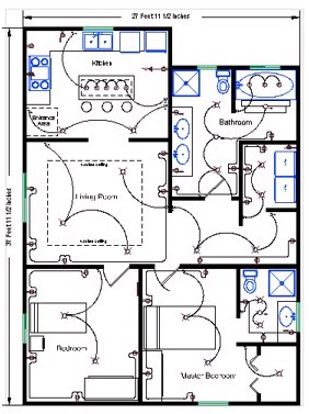
Floorplans With Power Low Voltage And Structured Wiring Symbols.

House And Home Wiring Diagram And Electrical System.
Tuesday, June 4, 2013
Wire Lights Switchehow

Way Switch Wiring Diagram Variation 6 Electrical Online.

Two Way Light Switch Using 3 Core Cable.

How To Wire Two Lights On One Switch Ehow Com.

Wiring Diagram 3 Way Switch.

Way Light Diagram Two Way Switching Wiring Diagram.

Outdoor Lighting Wiring Diagram 2 Gang Switch.

Way Switch Wiring Diagram Variation 5 Electrical Online.

Toyota Fj Cruiser Stop Light Switch Wiring Circuit Schematic.

One Gang Switch For Multiple Lights 2 Gang Switch.

Photo Albums Wiring Diagrams Two Gang Two Way Switch.
Hubbell Wiring Device Kellems Platewall Gang

Hubbell Wiring Device Kellems Ss13 Wall Plate 1 Gang Be The First.

Hubbell Wiring Device Kellems Sa3825 Floor Box Cover Rectangular.

Hubbell Wiring Device Kellems Cpb21 Pendant Station Be The First To.

Hubbell Wiring Device Kellems Hbl5666ca Plug Angle 6 15 Nema Be.

Hubbell Wiring Device Kellems Ss1 Plate Wall 1 Gang Be The First.

Hubbell Wiring Devices.

Hubbell Wiring Device Kellems Shc1023 Cord Connector 375 5 In L 1.

Hubbell Wiring Device Kellems Hbl9367 Receptacle 50 A 250 V Be The.

Hubbell Wiring Device Kellems S1spffbl Sub Plate Furniture Feed.

Hubbell Wiring Device Kellems Hbl9431c Plug 30a Nema 14 30p Be The.
Honeywell Storehoneywell Rth6350dprogrammable Thermostat

To The Thermostat From The Left Wiring To The Roof Is Indicated On.
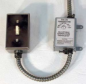
In Philadelphia 215 352 5963 Wiring Up A Thermostat To A Fan.
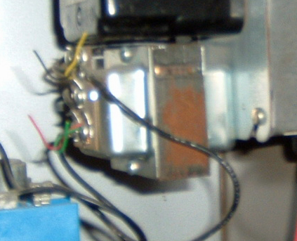
Name Thermostat Transformer Jpgviews 2372size 130 4 Kb.
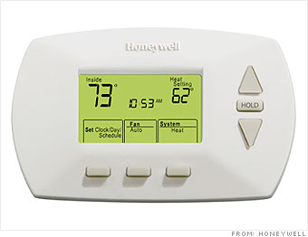
Knock 4 000 Off Your Utility Bill Use Time Settings For Heat 3.

Converting To Automag Using Teo Wire Thermostats Diagram.
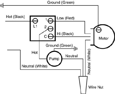
Rsk 2 Wiring Diagram.

Honeywell Store Honeywell Rth6350d 5 2 Programmable Thermostat.
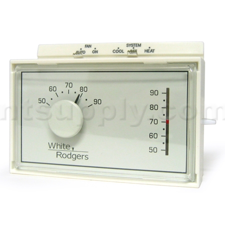
Free 1 Heat 1 Cool Thermostat Horizontal White Rodgers 1f56n 444.

Honeywell Thermostat Wiring Diagram Electrical Reply.

Hi Regarding Thermostat For Lizard Enclosure Page 2 Ask Me Help.
Subscribe to:
Posts (Atom)