Showing posts with label based. Show all posts
Showing posts with label based. Show all posts
Tuesday, February 4, 2014
Hardware MoodLamp Based on LED
Long time ago I came across this page http://tobe.nimio.info/project/moodlamp, where Toon Beerten created a Moodlamp using a PIC16F628 µC. I remember that back then I didn’t have much knowledge on µC’s programming, so the first thing I did was to buy a Arduino board, and since that time I have been learning a lot and making many different projects with it…

Time has passed, I’ve built the breadboard prototype, then the first version, using only one layer (which is a good version if you want to etch your own PCB). Always wanted to make the project public as an Open Hardware, but due my lack of time, I never did, until I arrive in Genova. I then decided to make a second version of the board, two layers, the ability to program the µC without removing it from the socket (for programing you will need an Arduino, FTDI or USB-to-serial cable) and some available pins for those who want’s to add more features to the board, like a temperature sensor or another kind of sensor.
Here you will find the information on how to build your own MoodLamp with simple electronic components. I am also planing on selling the MoodLamp kits, if you are interested, please leave a comment below (you can always make a Paypal donation so I can buy some beers!)
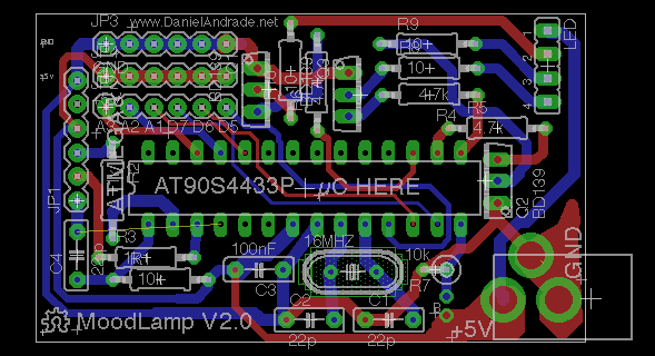
Here you will find the information on how to build your own MoodLamp with simple electronic components. I am also planing on selling the MoodLamp kits, if you are interested, please leave a comment below (you can always make a Paypal donation so I can buy some beers!)
Tuesday, March 19, 2013
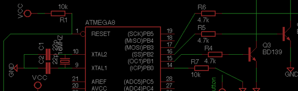
Comparator Based Crystal Oscillator
Although a simple crystal oscillator may be built from one comparator of an LT1720/LT1721, this will suffer from a number of inherent shortcomings and design problems. Although the LT1720/LT1721 will give the correct logic output when one input is outside the common mode range, additional delays may occur when it is so operated, opening the possibility of spurious operating modes. Therefore, the DC bias voltages at the inputs have to be set near the center of the LT1720/LT1721’s common mode range and a resistor is required to attenuate the feedback to the non-inverting input. Unfortunately, although the output duty cycle for this circuit is roughly 50%, it is affected by resistor tolerances and, to a lesser extent, by comparator offsets and timings.
 If a 50% duty cycle is required, the circuit shown here creates a pair of complementary outputs with a forced 50% duty cycle. Crystals are narrow-band elements, so the feedback to the non-inverting input is a filtered analogue version of the square-wave output. The crystal’s path provides resonant positive feedback and stable oscillation occurs. Changing the non-inverting reference level can vary the duty cycle. The 2k-680Ω resistor pair sets a bias point at the comparator + (Comparator IC1a) and – (Comparator IC1b) input. At the complementary input of each comparator, the 2k-1.8k-0.1µF path sets up an appropriate DC average level based on the output.
IC1b creates a complementary output to IC1a by comparing the same two nodes with the opposite input. IC2 compares band-limited versions of the outputs and biases IC1a’s negative input. IC1a’s only degree of freedom to respond is variation of pulse width; hence the outputs are forced to 50% duty cycle. The circuit operates from 2.7V to 6V. When ‘scoping the oscillator output signal, a slight dependence on comparator loading, will be noted, so equal and resistive loading should be used in critical applications. The circuit works well because of the two matched delays and rail-to-rail outputs of the LT1720.
Continue Reading..
If a 50% duty cycle is required, the circuit shown here creates a pair of complementary outputs with a forced 50% duty cycle. Crystals are narrow-band elements, so the feedback to the non-inverting input is a filtered analogue version of the square-wave output. The crystal’s path provides resonant positive feedback and stable oscillation occurs. Changing the non-inverting reference level can vary the duty cycle. The 2k-680Ω resistor pair sets a bias point at the comparator + (Comparator IC1a) and – (Comparator IC1b) input. At the complementary input of each comparator, the 2k-1.8k-0.1µF path sets up an appropriate DC average level based on the output.IC1b creates a complementary output to IC1a by comparing the same two nodes with the opposite input. IC2 compares band-limited versions of the outputs and biases IC1a’s negative input. IC1a’s only degree of freedom to respond is variation of pulse width; hence the outputs are forced to 50% duty cycle. The circuit operates from 2.7V to 6V. When ‘scoping the oscillator output signal, a slight dependence on comparator loading, will be noted, so equal and resistive loading should be used in critical applications. The circuit works well because of the two matched delays and rail-to-rail outputs of the LT1720.
Subscribe to:
Posts (Atom)