Showing posts with label electrical. Show all posts
Showing posts with label electrical. Show all posts
Saturday, September 21, 2013
1979 Jeep CJ Electrical Wiring Diagram
 |
| 1979 Jeep CJ Elecrical Wiring Diagram |
The part of 1979 Jeep CJ Electrical Wiring Diagram: accessory feed, air conditioner compressor, anti diesel solenoid, back up lamps, manual transmission, battery, boy, brake, cogar lighter, capacitor, chassis, marker & reflector, module assembly, neutral safety switch, oil lamp gauge, oil pressure sender, panel lamp, parking brake, park & signal lamp, resistor heater blower moor, splice, coil 6 cylinder, dimmer switch, distributor, electric choke, fuel gauges, fuel sender, ground fan lamp feed, headlamp, heater motor, ignition switch, horn relay, kick down, starting motor, stop lamp, tail & stop lamp, temperature gauge, temperature sender, windshield wiper, washer.
Thursday, May 30, 2013
Wiring Regulationssetting Standards Electrical Installations

Iee Wiring Regulations.

City And Guilds Exam Success Iee Wiring Regulations Paperback By.

Guide To The Wiring Regulations 2008 Iee Wiring Regulations Bs 7671.

17th Edition Iee Wiring Regulations.

Iee Wiring Regulations Bs 7671 2008 And Part P Of Building.

Bs 7671 Iee Wiring Regulations 17th Edition.
Iee Wiring Regulations Design And Verification Of Electrical.

Work Updated To Iee Wiring Regulations 17th Edition Bs 7671 2008.

Iee Wiring Regulations Setting Standards In Electrical Installations.

Bathroom Lighting Zones.
Wednesday, March 27, 2013
Nissan 370z Wiring Diagram Body Electrical Systemcircuit
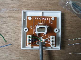
Guide To Rewiring Internal Uk Phone Wiring.
Cable Modem With Either Airport Extreme Or Time Capsule Macrumors.

Nissan 370z Wiring Diagram And Body Electrical System Circuit.

Application Diagrams.
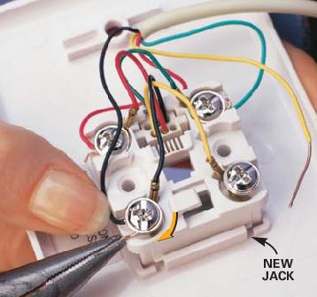
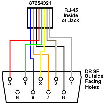
Residential Telephone Wiring Basics.

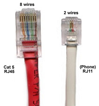
Telephone Wire Colour Codes.

Telephone Socket Wiring Diagram.

Volt Relay Circuit Diagram For Controlling Ac Current Arya.

Dodge Dakota Radio Wiring Diagram 1998 Dodge Ram 1500 Wiring Diagram.
Wiring Diagram.
Friday, March 22, 2013
Electrical Wiring United Kingdomwikipedia Free

Have Separate Wiring To Carry Energy Loads To And From The House.

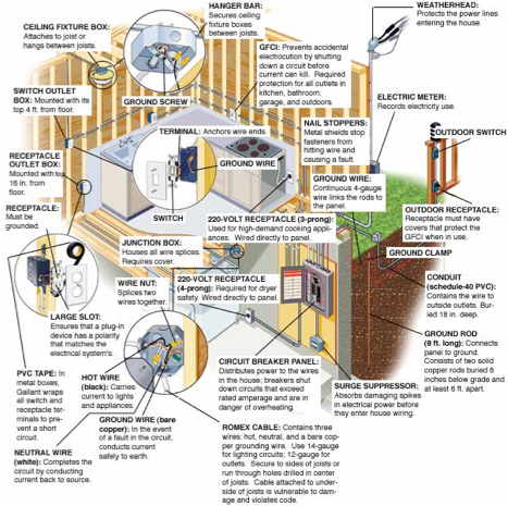
Residential Circuit Diagram Electrical Wiring Information.

Outdoor Lighting Wiring Diagram 2 Gang Switch.

House Wiring.
Big Steps In Building Change Our Wiring To 12 Volt Dc.

House Wiring Cables Supplier Exporter Orient Cables India Private.

What Is Three Phase House Wiring Dexknows Com.

Electrical Wiring In The United Kingdom Wikipedia The Free.

New Electrical Service Home Residential Wiring Diy Advice.

House Wiring Accessories Supplier Exporter Precision Electricals.
Tuesday, March 19, 2013
Electrical Isolation For I2C Bus
When the SDA (Serial DAta) lines on both the left and right lines are 1, the circuit is quiescent and optoisolators IC1 and IC2 are not actuated. When the SDA line at the left becomes 0, current flows through the LED in IC1 via R2. The SDA line at the right is then pulled low via D2 and IC1. Optoisolator IC2 does not transfer this 0 to the left, because the polarity of the LED in IC2 is the wrong way around for this level. This arrangement prevents the circuit holding itself in the 0 state for ever. As is seen, the circuit is symmetrical. So, when the SDA line at the right is 0, this is transferred to the left. The lower part of the diagram, intended for the SCL (Serial CLock) line, is identical to the upper part.

Resistors R1, R4, R5, and R8, are the usual 3.3 kΩ pull-up resistors that are obligatory in each I2C line. If these resistors are already present elsewhere in the system, they may be omitted here. The current drawn by the circuit is slightly larger than usual since the pull-up resistors are shunted by the LEDs in the optoisolators and their series resistors. Nevertheless, it remains within the norms laid down in the I2C specification.
Continue Reading..

Electrical Isolation For I2C Bus Circuit Diagram
Resistors R1, R4, R5, and R8, are the usual 3.3 kΩ pull-up resistors that are obligatory in each I2C line. If these resistors are already present elsewhere in the system, they may be omitted here. The current drawn by the circuit is slightly larger than usual since the pull-up resistors are shunted by the LEDs in the optoisolators and their series resistors. Nevertheless, it remains within the norms laid down in the I2C specification.
Subscribe to:
Posts (Atom)