Showing posts with label simple. Show all posts
Showing posts with label simple. Show all posts
Friday, December 27, 2013
Simple Voltage controlled current source with grounded source and load
This is a Simple Voltage controlled current source with grounded source and load. This is a simple, precise voltage-controlled current source. Bipolar supplies will permit bipolar output. Configurations featuring a grounded voltage- control source and a grounded load are usually more complex and depend upon several components for stability.Voltage-controlled-current-source-with-grounded-source-and-load. In this circuit, accuracy and stability almost entirely depend upon the 100-0 shunt.
Voltage controlled current source circuit diagram

Sourced by : Simple Voltage controlled current source with grounded source and load

Tuesday, December 17, 2013
Simple Self Oscillating Switching Converter Circuit Diagram
This is a Simple Self Oscillating Switching Converter Circuit Diagram. Regulation is provided by taking the rectified output of the sense winding and applying it as a bias to the base of Q2 via zener Dl. The collector of Q2 then removes drive from the gate of Ql.
Therefore, if the . output voltage should increase, Q2 removes the drive to Ql earlier, shortening the on time, and the output voltage will remain the same. De outputs are obtained by merely rectifying and filtering secondary windings, as done by D5 and C4.
Self Oscillating Switching Converter Circuit Diagram

Monday, May 27, 2013
Simple ufo Detector Circuit Diagram
This is some what different concept But here I have used very simple method.Most of people in the world find UFOs by looking at the sky most of time we can see some rich people buy cameras and focus them to the sky.But those unites are so expensive here I have shown you very simple diagram.When UFOs pass our area normally those machines out put high magnetic field so here we have used that magnetic power to detect them.when a UFO passes your area the magnet of your circuit will move. then the circuit will be switched on

Note
# Use 3V power supply
# Click this to make UM66 music circuit
Continue Reading..
Note
# Use 3V power supply
# Click this to make UM66 music circuit
Thursday, April 4, 2013
Simple Shadow Detector Alarm
This is also known as Sun up alarm, in this circuit you can set the LDR’s sensitivity by 100k potentiometer, you can set it with any lamp around your room (tube light, bulb, LED etc) by varrying the 100k potentiometer. We can also control the buzzer time by 1M potentiometer
You can Enhance this project and set the sensitivity of the LDR with a lazer light and keep it on the way of any door circuit at one side and lazer at other side of the door and a then you can make this project to buzz as soon as some one enters in a room
I personally set this project in my room with sensitivity of tube light and whenever i came in and turn my room’s tube light on
rookieelectronics
Circuit Diagram:

You can Enhance this project and set the sensitivity of the LDR with a lazer light and keep it on the way of any door circuit at one side and lazer at other side of the door and a then you can make this project to buzz as soon as some one enters in a room
I personally set this project in my room with sensitivity of tube light and whenever i came in and turn my room’s tube light on
rookieelectronics
Parts Required:
|
Simple 2 1 Surround Speaker System Circuit Diagram

Part List
| Component No: | Value | Usage |
| All C1 | 100MF | Grounding |
| All C2 | 100nF | Grounding |
| All C3 | 100nF | Grounding |
| All C4 | 100MF | Grounding |
| All C5 | 100MF | Feedback |
| All C6 | 100MF | Audio Coupling |
| All C7 | 220nF | Noise Grounding |
| All R1 | 1K | |
| All R2 | 10K ( Not 1K ) | |
| All R3 | 22K | |
| All R4 | 22K (Not 1K ) | |
| All RV1 | 100K | Volume Controlling |
| All D1 To D2 | IN4007 | Potential Breaking |
| U1 To U6 | TDA2030 | Amplification |
Applications
* 2.1 Surround Amplifier
* 2.1 Home Theater
Friday, March 29, 2013
Simple Li Ion Battery Charger
The LP2951 regulator is manufactured by National Semiconductors. The choice of values is from an application note Battery Charging, written by Chester Simpson. Diode D1 can be any diode from the 1N00x series, whichever is conveniently available. It functions as a blocking diode, to prevent a back flow of current from the battery into the LP2951 when the input voltage is disconnected. Charging current is about 100+mA, which is the internally-limited maximum current of the LP2951. For those wondering, this is compatible with just about any single-cell li-ion battery since li-ion can generally accept a charging current of up to about 1c (i.e. charging current in mA equivalent to their capacity in mAh, so a 1100mAh li-ion cell can be charged at up to 1100mA and so on).
 A lower charging current just brings about a correspondingly longer charge time. IMHO 100mA is quite low, low enough that the circuit can be used for an overnight charger for many typical single-cell li-ion batteries. The resistors are deliberately kept at large orders of magnitude (tens/hundred Kohm and Mohm range) to keep the off-state current as low as possible, at about 2?A. Resistor tolerances should be kept at 1% for output voltage accuracy. The 50k pot allows for an output voltage range between 4.08V to 4.26V - thus allowing calibration as well as a choice between a charging voltage of 4.1V or 4.2V depending on the cell to be charged. The capacitors are for stability, especially C2 which prevents the output from ringing/oscillating.
Parts List
IC1 = LP2951, voltage regulator
D1 = 1N4002, General purpose diode
R1 = 2M, 1%, metal-film
R2 = 806K, 1%, metal-film
P1 = 50K, potentiometer
C1 = 0.1uF, polyester
C2 = 2.2uF/16V, electrolytic
C3 = 330pF, ceramic
 A lower charging current just brings about a correspondingly longer charge time. IMHO 100mA is quite low, low enough that the circuit can be used for an overnight charger for many typical single-cell li-ion batteries. The resistors are deliberately kept at large orders of magnitude (tens/hundred Kohm and Mohm range) to keep the off-state current as low as possible, at about 2?A. Resistor tolerances should be kept at 1% for output voltage accuracy. The 50k pot allows for an output voltage range between 4.08V to 4.26V - thus allowing calibration as well as a choice between a charging voltage of 4.1V or 4.2V depending on the cell to be charged. The capacitors are for stability, especially C2 which prevents the output from ringing/oscillating.
Parts List
IC1 = LP2951, voltage regulator
D1 = 1N4002, General purpose diode
R1 = 2M, 1%, metal-film
R2 = 806K, 1%, metal-film
P1 = 50K, potentiometer
C1 = 0.1uF, polyester
C2 = 2.2uF/16V, electrolytic
C3 = 330pF, ceramic
Thursday, March 28, 2013
Simple AudioTone Control Circuit
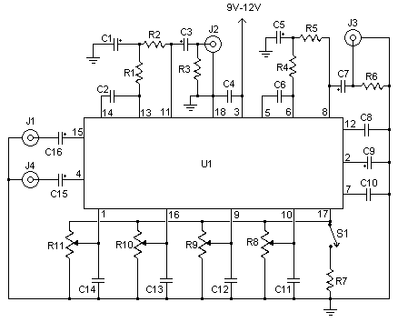
This simple AudioTone Control can be acclimated in may audio applications. It can be added to amplifers, acclimated as a angle abandoned ascendancy module, or alike congenital into new and agitative instruments. Its one IC architecture makes it a actual bunched circuit, as alone a few abutment apparatus are required. Plus, it does not use a bifold ability supply. This agency that the ambit will run from 9V to 15V (although the bass will be a little anemic at 9V). The ambit is by Robert Barg and originally appeared in the Think Tank cavalcade of the May 1998 affair of Popular Electronics.
Simple AudioTone Control Circuit Part List
C1, C3, C5, C7, C15, C16 2.2uf Electrolytic Capacitor
C2, C6 0.05uF Ceramic Disc Capacitor
C4 0.22uF Disc Capacitor
C8, C10 0.015uF Ceramic Disc Capacitor
C9 100uF Electrolytic Capacitor
C11, C12, C13, C14 0.1uF Ceramic Disc Capacitor
R1, R4 10K 1/4W Resistor
R2, R5 33K 1/4W Resistor
R3, R6 4.7K 1/4W Resistor
R7 2.2K 1/4W Resistor
R8, R9, R10, R11 50K Linear Pot
U1 TDA1524A Tone Control IC
S1 SPST Switch
J1, J2, J3, J4 4 RCA Jacks
MISC Board, Wire, Knobs, 18 Pin Socket
NOTES
Simple AudioTone Control Circuit Part List
C1, C3, C5, C7, C15, C16 2.2uf Electrolytic Capacitor
C2, C6 0.05uF Ceramic Disc Capacitor
C4 0.22uF Disc Capacitor
C8, C10 0.015uF Ceramic Disc Capacitor
C9 100uF Electrolytic Capacitor
C11, C12, C13, C14 0.1uF Ceramic Disc Capacitor
R1, R4 10K 1/4W Resistor
R2, R5 33K 1/4W Resistor
R3, R6 4.7K 1/4W Resistor
R7 2.2K 1/4W Resistor
R8, R9, R10, R11 50K Linear Pot
U1 TDA1524A Tone Control IC
S1 SPST Switch
J1, J2, J3, J4 4 RCA Jacks
MISC Board, Wire, Knobs, 18 Pin Socket
NOTES
- S1 is a contour control. Volume is controlled by R11. Balance is controlled by R10. R9 and R8 control bass and treble, respectivly.
- J1 is the left input, J4 is the right input. J2 is the left output, J3 is the right output.
- The circuit is designed to accept line level or mic level inputs. if you are going to be using a stronger signal, a voltage divider will be necessary to cut it down to proper levels.
- You can, of course, skip J1-J4 if you plan to integrate this circuit into another.
Monday, March 25, 2013
Simple Electronic Quiz Switch
One of the common rounds in the quizzes is the buzzer round. We are describing here a simple electronic circuit that can be used in any test or quiz competition. In this circuit, only four persons can participate, and every participant is assigned a certain number. Whenever a switch is pressed, the circuit locks the remaining three entries. At the same time, an alarm sounds and the designated switch number is displayed on the seven segment LED display.When a player presses his switch, the corresponding output of IC1 goes high. Let us suppose, when switch S1 is pressed, D1 input of IC1 goes low and its corresponding output Q1 goes high. As a result, current passes through D5 to piezo buzzer PZ1, which creates a beep. At the same time, current also passes through diodes D6-D7 to show the number on the LED display.
Circuit diagram:

Simple Electronic Quiz Switch Circuit Diagram
Similarly, when any other switch (S2-S4) is pressed, the corresponding number gets displayed on seven segment displaying DIS1 and buzzer sounds. Switch S5 is used to reset the display exclusively. Switch S5 is a push to on switch. The circuit is powered by 9V battery. Assemble the circuit on a general purpose PCB and enclose it in a suitable case along with seven segment display and piezo buzzer. The assembled circuit can be kept near the host and the switches connected through the external can be assigned to the players.
http://streampowers.blogspot.com/2012/06/simple-electronic-quiz-switch.html
Saturday, March 23, 2013
Simple Current Controlled LED Tube Light Circuit Diagram
Note: This circuit is developed by Mr.Seetharaman
for readers of CircuitsToday. This particular circuit has been kept so
simple for people who has limited access to components or in other words
this is an emergency light that you can build with minimum components.
In addition to circuit diagram, He has shared photographs of the
prototype he made in National emergency light and a PCB design.


Simple Current Controlled LED Tube Light Circuit Diagram
Subscribe to:
Posts (Atom)