Showing posts with label line. Show all posts
Showing posts with label line. Show all posts
Wednesday, March 27, 2013
Switch Line Connectors Switches Connected

Installing A New Light And Switch.
Power Light Switch Switch.
Light And Outlet 2 Way Switch Wiring Diagram.

Wiring A Light Switch For A Ceiling Light Diy Project.
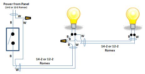
How To Wire Two Lights Controlled From One Switch.

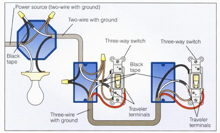
Way Switch Wiring Diagram Variation 3 Electrical Online.
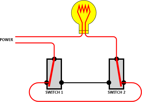
Switch The Line Connectors Of The Two Switches Are Connected In.

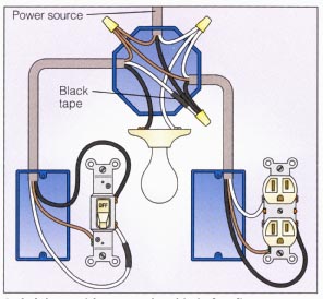
Wiring A Switched Outlet Wiring Diagram Electrical Online.

Wiring A Switch Light First.

Wiring A Double Switch Handyman Guide For Home Improvement And.
Saturday, March 23, 2013
Telephone Line Indicator
With the aid of an (old) moving coil instrument it is very little effort to make a simple voltmeter that, at a glance, indicates the status of a telephone line. Because the input impedance of this circuit is very high, there is no problem in having it permanently connected to the line, since it only draws a tiny amount of current. The schematic shows that the circuit consists of no more than a series resistor, a bridge rectifier and a moving coil meter. The value of the resistor depends on the sensitivity of the moving coil meter. In his prototypes, the author used old VU meters that require 250µA for full-scale deflection. A resistor value of 390 kΩ appeared to be optimal for these meters.

For a 100µA instrument, this resistor value will have to be increased to about 680 kΩ. The starting point, when selecting a resistor value is that when the telephone is not in use, the meter should deflect about 2/3rd of full scale. The amount of meter deflection indicates the three different states of the telephone line: 1. The deflection is very small: the line is in use (voltage 5 to 12 V). 2. The deflection is 2/3rd of full scale: the line is not in use (voltage typically 48 V). 3. Full-scale deflection: ring signal (60 to 90 V AC). Because the idle voltage and certainly the ring voltage are high enough to be dangerous, it is recommended that the circuit is constructed in such a way that it presents no hazard when touched.
Continue Reading..
For a 100µA instrument, this resistor value will have to be increased to about 680 kΩ. The starting point, when selecting a resistor value is that when the telephone is not in use, the meter should deflect about 2/3rd of full scale. The amount of meter deflection indicates the three different states of the telephone line: 1. The deflection is very small: the line is in use (voltage 5 to 12 V). 2. The deflection is 2/3rd of full scale: the line is not in use (voltage typically 48 V). 3. Full-scale deflection: ring signal (60 to 90 V AC). Because the idle voltage and certainly the ring voltage are high enough to be dangerous, it is recommended that the circuit is constructed in such a way that it presents no hazard when touched.
Subscribe to:
Posts (Atom)